In this project we will make traffic lights animation in England, not know is its setting same with traffic lights in Indoensia. For this project certain we use led with color red, yellow, and green. Now we are going to look for how resistance value will be used for each.
Look for resistance value for red led
According to Red Led 5mm diffused datasheet, its Forward Voltage (VF) is 2 Volt and maximum is 2,5 Volt. So red led safe to operate at voltage range 2 - 2,5 Volt. According to Red Led 5mm diffused datasheet its Forward Current (IF) is 20 mA. Output voltage from Arduino is 5 Volt
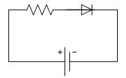
On series circuit like picture above, Voutput = VLed + VResistor.
If we use operating voltage 2 Volt for red led, then voltage for resistor (VResistor) is Voutput – VLed = (5 – 2) Volt = 3 Volt, forward current (IF) on red led is 20 mA, cause its circuit is series, certain current flows on resistor is also 20 mA, so that resistance value is needed is:

If we use operating voltage 2,5 Volt for red led, then voltage for resistor (VResistor) is Voutput – VLed = (5 – 2,5) Volt = 2,5 Volt, forward current (IF) on red led is 20 mA, cause its circuit is series, certain current flows on resistor is also 20 mA, so that resistance value is needed is:

So for red led can be used resistor with value range 125 – 150 Ω
Look for resistance value for yellow led
According to Yellow Led 5mm diffused datasheet, its Forward Voltage (VF) is 2,1 Volt and maximum is 2,5 Volt. So yellow led safe to operate at voltage range 2,1 - 2,5 Volt. According to Yellow Led 5mm diffused datasheet its Forward Current (IF) is 20 mA. Output voltage from Arduino is 5 Volt
On series circuit like picture above, Voutput = VLed + VResistor.
If we use operating voltage 2,1 Volt for yellow led, then voltage for resistor (VResistor) is Voutput – VLed = (5 – 2,1) Volt = 2,9 Volt, forward current (IF) on yellow led is 20 mA, cause its circuit is series, certain current flows on resistor is also 20 mA, so that resistance value is needed is:

If we use operating voltage 2,5 Volt for yellow led, then voltage for resistor (VResistor) is Voutput – VLed = (5 – 2,5) Volt = 2,5 Volt, forward current (IF) on yellow led is 20 mA, cause its circuit is series, certain current flows on resistor is also 20 mA, so that resistance value is needed is:

So for yellow led can be used resistor with value range 125 – 145 Ω
Look for resistance value for green led
According to Green Led 5mm diffused datasheet, its Forward Voltage (VF) is 2,2 Volt and maximum is 2,6 Volt. So green led safe to operate at voltage range 2,2 - 2,6 Volt. According to Green Led 5mm diffused datasheet its Forward Current (IF) is 20 mA. Output voltage from Arduino is 5 Volt
On series circuit like picture above, Voutput = VLed + VResistor.
If we use operating voltage 2,1 Volt for green led, then voltage for resistor (VResistor) is Voutput – VLed = (5 – 2,1) Volt = 2,9 Volt, forward current (IF) on green led is 20 mA, cause its circuit is series, certain current flows on resistor is also 20 mA, so that resistance value is needed is:

If we use operating voltage 2,6 Volt for green led, then voltage for resistor (VResistor) is Voutput – VLed = (5 – 2,6) Volt = 2,4 Volt, forward current (IF) on green led is 20 mA, cause its circuit is series, certain current flows on resistor is also 20 mA, so that resistance value is needed is:

So for green led can be used resistor with value range 120 – 145 Ω
So got data:
For red led can be used resistor with value range 125 – 150 Ω
For yellow led can be used resistor with value range 125 – 140 Ω
For green led can be used resistor with value range 120 – 140 Ω
Because sahabat now have are 100 Ω resistor, 150 Ω resistor, and 220 Ω resistor for each 10, then one of solution can be made 2 of 100 Ω resistor series with 2 of 150 Ω resistor so that get resistor with resistance value 125 Ω which can be used for all three leds.
Actually there is no problem we use resistor with its resistance value is higher resistance value, just may be brightness of led will less dim, but will be danger if we use resistor with smaller resistance value can damage tools
So we need are Arduino, USB Cable, Breadboard, 1 of red led, 1 of yellow led, 1 of green led, jumper wires, 6 of 100 Ω resistor, and 6 of 150 Ω resistor.
The sketch are follows:
int ledDelay = 5000;
int redPin = 10;
int yellowPin = 9;
int greenPin = 8;
void setup()
{
pinMode(redPin, OUTPUT);
pinMode(yellowPin, OUTPUT);
pinMode(greenPin, OUTPUT);
}
void loop()
{
digitalWrite(redPin, HIGH);
delay(ledDelay);
digitalWrite(yellowPin, HIGH);
delay(2000);
digitalWrite(greenPin, HIGH);
digitalWrite(redPin, LOW);
digitalWrite(yellowPin, LOW);
delay(ledDelay);
digitalWrite(yellowPin, HIGH);
digitalWrite(greenPin, LOW);
delay(2000);
digitalWrite(yellowPin, LOW);
}
There is something new from this sketch code, can be understood: turn red led on, wait 5 seconds, turn yellow led on, wait 2 seconds, turn green led on and turn red led and yellow led off directly, wait 5 seconds, turn yellow led on and turn green led off directly, wait 2 seconds, turn yellow led off, and back again to start and like that continue...
its result can be watched on video follows:
hopefully useful... if there is something understood please contact sahabat... :)
Salam... :)
Look for resistance value for red led
According to Red Led 5mm diffused datasheet, its Forward Voltage (VF) is 2 Volt and maximum is 2,5 Volt. So red led safe to operate at voltage range 2 - 2,5 Volt. According to Red Led 5mm diffused datasheet its Forward Current (IF) is 20 mA. Output voltage from Arduino is 5 Volt
On series circuit like picture above, Voutput = VLed + VResistor.
If we use operating voltage 2 Volt for red led, then voltage for resistor (VResistor) is Voutput – VLed = (5 – 2) Volt = 3 Volt, forward current (IF) on red led is 20 mA, cause its circuit is series, certain current flows on resistor is also 20 mA, so that resistance value is needed is:
If we use operating voltage 2,5 Volt for red led, then voltage for resistor (VResistor) is Voutput – VLed = (5 – 2,5) Volt = 2,5 Volt, forward current (IF) on red led is 20 mA, cause its circuit is series, certain current flows on resistor is also 20 mA, so that resistance value is needed is:
So for red led can be used resistor with value range 125 – 150 Ω
Look for resistance value for yellow led
According to Yellow Led 5mm diffused datasheet, its Forward Voltage (VF) is 2,1 Volt and maximum is 2,5 Volt. So yellow led safe to operate at voltage range 2,1 - 2,5 Volt. According to Yellow Led 5mm diffused datasheet its Forward Current (IF) is 20 mA. Output voltage from Arduino is 5 Volt
On series circuit like picture above, Voutput = VLed + VResistor.
If we use operating voltage 2,1 Volt for yellow led, then voltage for resistor (VResistor) is Voutput – VLed = (5 – 2,1) Volt = 2,9 Volt, forward current (IF) on yellow led is 20 mA, cause its circuit is series, certain current flows on resistor is also 20 mA, so that resistance value is needed is:
If we use operating voltage 2,5 Volt for yellow led, then voltage for resistor (VResistor) is Voutput – VLed = (5 – 2,5) Volt = 2,5 Volt, forward current (IF) on yellow led is 20 mA, cause its circuit is series, certain current flows on resistor is also 20 mA, so that resistance value is needed is:
So for yellow led can be used resistor with value range 125 – 145 Ω
Look for resistance value for green led
According to Green Led 5mm diffused datasheet, its Forward Voltage (VF) is 2,2 Volt and maximum is 2,6 Volt. So green led safe to operate at voltage range 2,2 - 2,6 Volt. According to Green Led 5mm diffused datasheet its Forward Current (IF) is 20 mA. Output voltage from Arduino is 5 Volt
On series circuit like picture above, Voutput = VLed + VResistor.
If we use operating voltage 2,1 Volt for green led, then voltage for resistor (VResistor) is Voutput – VLed = (5 – 2,1) Volt = 2,9 Volt, forward current (IF) on green led is 20 mA, cause its circuit is series, certain current flows on resistor is also 20 mA, so that resistance value is needed is:
If we use operating voltage 2,6 Volt for green led, then voltage for resistor (VResistor) is Voutput – VLed = (5 – 2,6) Volt = 2,4 Volt, forward current (IF) on green led is 20 mA, cause its circuit is series, certain current flows on resistor is also 20 mA, so that resistance value is needed is:
So for green led can be used resistor with value range 120 – 145 Ω
So got data:
For red led can be used resistor with value range 125 – 150 Ω
For yellow led can be used resistor with value range 125 – 140 Ω
For green led can be used resistor with value range 120 – 140 Ω
Because sahabat now have are 100 Ω resistor, 150 Ω resistor, and 220 Ω resistor for each 10, then one of solution can be made 2 of 100 Ω resistor series with 2 of 150 Ω resistor so that get resistor with resistance value 125 Ω which can be used for all three leds.
Actually there is no problem we use resistor with its resistance value is higher resistance value, just may be brightness of led will less dim, but will be danger if we use resistor with smaller resistance value can damage tools
So we need are Arduino, USB Cable, Breadboard, 1 of red led, 1 of yellow led, 1 of green led, jumper wires, 6 of 100 Ω resistor, and 6 of 150 Ω resistor.
The sketch are follows:
int ledDelay = 5000;
int redPin = 10;
int yellowPin = 9;
int greenPin = 8;
void setup()
{
pinMode(redPin, OUTPUT);
pinMode(yellowPin, OUTPUT);
pinMode(greenPin, OUTPUT);
}
void loop()
{
digitalWrite(redPin, HIGH);
delay(ledDelay);
digitalWrite(yellowPin, HIGH);
delay(2000);
digitalWrite(greenPin, HIGH);
digitalWrite(redPin, LOW);
digitalWrite(yellowPin, LOW);
delay(ledDelay);
digitalWrite(yellowPin, HIGH);
digitalWrite(greenPin, LOW);
delay(2000);
digitalWrite(yellowPin, LOW);
}
There is something new from this sketch code, can be understood: turn red led on, wait 5 seconds, turn yellow led on, wait 2 seconds, turn green led on and turn red led and yellow led off directly, wait 5 seconds, turn yellow led on and turn green led off directly, wait 2 seconds, turn yellow led off, and back again to start and like that continue...
its result can be watched on video follows:
hopefully useful... if there is something understood please contact sahabat... :)
Salam... :)

0 komentar:
Posting Komentar